Device#
Concept#
A device is a key concept of Tango Controls. This concept can be directly linked to the notion of microservice: 1 device = 1 microservice.
A device can represent:
A piece of equipment (eg: a power supply),
Multiple pieces of equipment (eg: a set of 4 motors driven by the same controller),
A set of software functions (eg: image processing),
A group of devices representing a subsystem
The Tango Device abstracts away the specific nature of a piece of equipment, i.e. it hides the specific implementation details from the user who does not need to care about communication protocols etc. and provides the user with a model which speaks their languages e.g. physical or engineering parameters.
In the real world, devices vary from serial line devices to devices interfaced by field-bus to memory mapped VME cards or PC cards to entire data acquisition systems. The definition of a device depends very much on the user’s requirements. In the simple case a device server can be used to hide the serial line protocol required to communicate with a device. For more complicated devices the device server can be used to hide the entire complexity of the device timing, configuration and acquisition cycle behind a set of high level commands.
Description#
A device is the basic entity of the control system. In the Tango world, everything is a device. A Device has an interface composed of commands and attributes, which provides the service of the device. It also has properties, stored in the relational database, which are generally used as configuration settings.
Each device belongs to a Device Class.
Devices are created by Device Servers, which will call the device classes. Each device is created and stored in a process called a device server. This will call the device class that the device belongs to. Devices are configured at runtime via a set of properties which are stored in the database.
All devices support a black box where client requests for attributes or operations are recorded. This feature allows easier debugging session for device already installed in a running control system.
Device hierarchy#
A Tango control system can be hierarchically organized.
At the lower level, we find elementary devices which are associated with equipments, e.g. a vacuum pump, a motor, an I/O card.
At higher levels, the devices are « logical ». These devices, based on the lower-level devices, manage and represent a subset of the control system. This is usually a synthetic view of a set of equipments with a high-level steering (functions can perform sequences of actions on several basic devices).
For example, a high-level device achieves “complex” features. This device is usually bound to evolve regardless of the hardware. Therefore, it is necessary to separate and segregate responsibilities related to the logic functionality and those related to hardware interfaces.
It is possible to access any other device from every device at every level.
The following diagram illustrates the concept of hierarchy of devices:
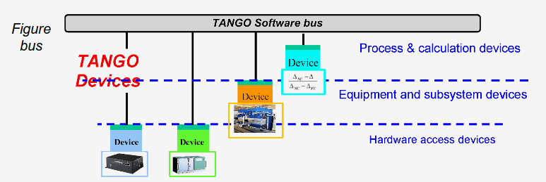
The software bus view of devices#
Hierarchical view of devices#
Device State#
Every Tango device has a state implemented by a finite state machine. It reflects the internal state of the system it represents.
The available states are limited to:
ON, OFF, CLOSE, OPEN, INSERT, EXTRACT,
MOVING, STANDBY, FAULT, INIT,
RUNNING, ALARM, DISABLE, UNKNOWN
A color code is associated to each state and is used in the main GUI tools to have a unified manner of representing the state of equipment.
State |
Colour |
Meaning |
|---|---|---|
ON |
green |
This state could have been called OK or OPERATIONAL. It means that the
device is in its operational state. (E.g. the power supply is giving its
nominal current, the motor is ON and ready to move, the instrument is
operating). This state is modified by the Attribute alarm checking of
the DeviceImpl:dev_state method. i.e if the state is ON and one
attribute has it’s quality factor to ALARM, then the state is modified
to ALARM
|
OFF |
white |
The device is in normal condition but is not active. e.g the
power supply main circuit breaker is open; the RF transmitter has no
power etc…
|
CLOSE |
white |
Synonym of OFF state. Can be used when OFF is not adequate for the
device e.g case of a valve, a door, a relay, a switch.
|
OPEN |
green |
Synonym of ON state. Can be used when ON is not adequate for the device
e.g case of a valve, a door, a relay, a switch.
|
INSERT |
white |
Synonym of OFF state. Can be used when OFF is not adequate for the
device. Case of insertable/extractable equipment, absorbers, etc…
This state is here for compatibility reason we recommend to use OFF or
CLOSE when possible.
|
EXTRACT |
green |
Synonym of ON state. Can be used when ON is not adequate for the device
Case of insertable/extractable equipment, absorbers, etc…
This state is here for compatibility reason we recommend to use ON or
OPEN when possible.
|
MOVING |
light blue |
The device is in a transitory state. It is the case of a device moving
from one state to another.( E.g a motor moving from one position to
another, a big instrument is executing a sequence of operation, a
macro command is being executed.)
|
STANDBY |
yellow |
The device is not fully active but is ready to operate. This state does
not exist in many devices but may be useful when the device has an
intermediate state between OFF and ON. E.g the main circuit breaker is
closed but there is no output current. Usually Standby is used when it
can be immediately switched ON. While OFF is used when a certain time
is necessary before switching ON.
|
FAULT |
red |
The device has a major failure that prevents it to work. For instance,
A power supply has stopped due to over temperature A motor cannot move
because it has fault conditions. Usually we cannot get out from this
state without an intervention on the hardware or a reset command.
|
INIT |
beige |
This state is reserved to the starting phase of the device server.
It means that the software is not fully operational and that the user
must wait
|
RUNNING |
dark green |
This state does not exist in many devices but may be useful when the
device has a specific state above the ON state. (E.g. the detector
system is acquiring data, An automatic job is being executed).
Note that this state is different from the MOVING state. It is not a
transitory situation and may be a normal operating state above the ON
state.
|
ALARM |
orange |
The device is operating but one of this attribute is out of range.
It can be linked to alarm conditions set by attribute properties or a
specific case. (E.g. temperature alarm on a stepper motor, end switch
pressed on a stepper motor, up water level in a tank, etc…) In alarm,
usually the device does it’s job but the operator has to perform an
action to avoid a bigger problem that may switch the state to FAULT.
|
DISABLE |
magenta |
The device cannot be switched ON for an external reason. e.g. the
power supply has it’s door open, the safety conditions are not
satisfactory to allow the device to operate
|
UNKNOWN |
grey |
The device cannot retrieve its state. It is the case when there is a
communication problem to the hardware (network cut, broken cable etc…).
It could also represent an incoherent situation
|
Device Class#
A device class is an abstraction of a device’s interface. The device class contains a complete description and implementation of the behavior of all members of that class. It defines the list of attributes, pipes and commands that are available for a certain device, which are then available to users and to other components of a Tango system.
A device class often relates to the specific hardware that it interfaces with, for example the SerialLine class defines an interface to communicate with serial line hardware.
All classes are derived from one root class thus allowing some common behavior for all devices. New device classes can also be constructed out of existing device classes. In this way a new hierarchy of classes can be built up in a short time. Device classes can use existing devices as sub-classes or as sub-objects. The practice of reusing existing classes is classical for Object Oriented Programming (OOP) and is one of its main advantages.
The DeviceClass#
Description#
Every device of the same class supports the same list of commands and hence this list of available commands is stored in the DeviceClass. For example, the structure returned by the info operation contains a URL to the documentation. This URL is the same for every device belonging to the same class and hence the documentation URL is a data member of this class. There should only be one instance of this class per device. The DeviceClass also stores the device list.
The DeviceClass is an abstract class because the two methods device_factory() and command_factory() are declared as pure virtual. The role of the device_factory() method is to create all the devices belonging to the device class. The role of the command_factory() method is to create one instance of all the classes needed to support device commands.
The DeviceClass also contains the attribute_factory method whose role is to store the name of all the device attributes. The default implementation of this method is an empty body representing a device without any attributes.
Contents#
The contents of this class can be summarize as:
The
command_handlermethodMethods to access data members
Signal related method (C++ specific)
Class constructor. It is protected to implements the Singleton pattern
Class data members like the class command list, the device list, etc
Device Server#
A Device Server is the process (i.e. the executable) that will create, run and serve instances of Devices. It must contain one or more Device Class, and can instantiate any number of Devices from those classes. Devices started from the same Device Server will run in the same process and hence share system resources such as memory, therefore it can be convenient to group devices into the same Device Server to optimise performance.
Each Device Server has a unique name made up of the name of the executable and a character string called the instance name. The pair of executable / instance name has to be unique in a Tango control system. The Device Server is responsible for querying the database to find out the list of Devices and their Device Classes to create. The Device Server must create the Devices, call their initialise routine and export them once the Device is created.
Device Servers create an internal device of their own called the Admin Device. This device is used to monitor and control the Device Server process lifecycle. It can perform tasks like restarting Devices, restarting the Device Server process, and starting or stopping polling.
Device Servers are linked to the Device classes that they will serve. Device Servers are usually managed by the Astor tool.

Runtime representation of a Device server with two classes A and B#
Summary#
Sometimes there are misuses of language regarding the concepts of a device, device server and a Tango class. Below is a summary:
DeviceClass class: a class defining the interface and state machine (only used in C++ device classes).
Device class: a class implementing the device control.
Device: An instance of a Device class giving access to the services of the DeviceClass class.
Device Server: process in which one or more Tango classes are executed (device server).
The diagrams below illustrate these concepts:
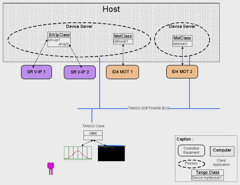
Tango Deployment#
A Device Server can host several Device classes, each class can be instantiated one or more times within the same device server. There are no specific rules regarding the maximum number of classes or the maximum number of instances operating within a single Device Server.
In particular cases, due to limitations imposed by the hardware or software interface, it is not always possible to run several instances of a Device class within the same Device Server:
Case of a DLL’s use: some DLLs can’t be used by two threads of the same process.
In other cases, it is useful to have multiple devices running in the same Device Server:
Case of motors: a single axis controller for 4 motors.